|
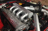
DIY High Flow 8V Head
I certainly am not an authority but I have
spent a lot of time researching and testing
8V 951 heads in a quest to develop a low
cost solution for larger motors.
Obviously the 16V is the best solution but
the cost is significant and in many cases
not practical. I wanted to do a head that
would perform well and keep in
line with the spirit of low cost Hybrid
Stroker motors. Outlined in this thread is
my current progress. Much thanks to all who
have helped me along the way, especially Sid
and MM.
The results and the total cost of the effort
are also outlined below:
951
Head.........................................$0
(head from my 2.5L)
47mm +2
Valves..............................$108
(set of 4,
see here)
Valve
Guides....................................$34
Valve
Seals......................................$36
Valve
Springs...................................$84
(set of 8,
see here)
Install
Guides...................................$160
Remove Valve
Seats.........................$48
Install New
Seats.............................$100
Surface
Cut......................................$60
Competition Valve
Job......................$265
Total Cost................$895
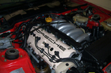
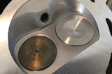
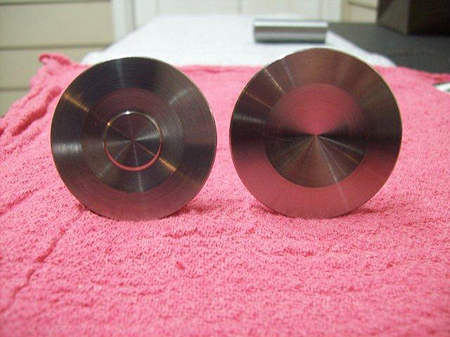
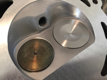
I started with the 8V 951 head from my 2.5L.
I disassembled the head, cleaned it, and
carefully inspected it. I inspected the
ceramic exhaust ports, inspected the deck
for pitting in the seal ring areas,
inspected how much the head had previously
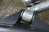
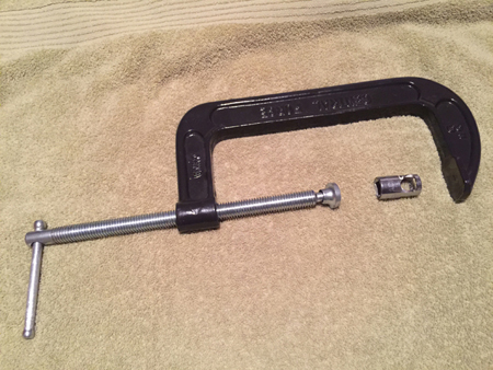
been decked. Some may laugh but below is a
picture of my valve spring compressor. It
consists of an 8" C clamp from Harbour
Freight and a modified socket (total cost $9
)
|
 |
|
|
 |
|
|
|
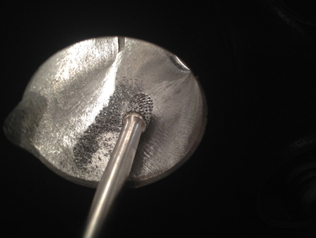
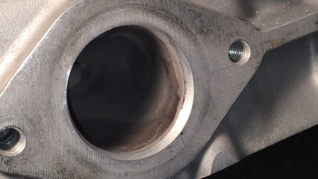
The next step was to do the initial porting.
I did much of the porting before the new
guides or intake seats were installed. In
this way I did not have to worry about
damaging the guides or the seats while
removing much of the port material. The
approach I took to porting was two fold.
One, to clean things up especially in the
throat area. I found on the flow bench that
cleaning up the bowl area right above the
throat resulted in improved flow. Secondly,
to increase the size of the intake port to
accommodate the bigger intake valve. My
approach was to maintain the port shape
while making it bigger. The intake valves I
used were 47mm which are 2mm bigger than the
stock intake valves. Therefore my approach
was to remove 1mm from all the walls of the
intake port as shown below. |
|
|
 |
|
|
 |
|
|
|
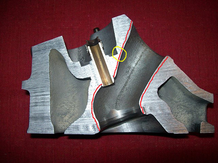
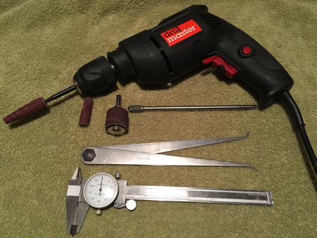
Below is a picture of all the tools I used
for doing the porting. All of the tools were
purchased at Harbour Freight with the
exception of the inside calipers and the
carbide bur (McMaster 4324A32). My porting
technique was slow and careful. I took A LOT
of initial measurements using the inside
calipers. I also used a technique in which I
used a drill bit to make several 1mm deep
holes as guides for how much material to
remove. I removed quite a bit of material
from around the guides. Be careful not to
remove too much material in the lead up to
the guide (see yellow circle above). I
probably spent over 20 hours porting the
intake ports. It is very important to make
the ports as similar as possible in order to
promote equal flow. My ports flowed within a
few cfm of each other on the flow bench. |
|
|
 |
|
|
 |
|
|
|
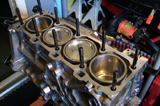
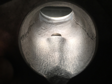
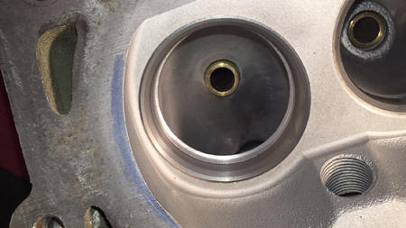
Once the initial porting was complete, the
head was taken to the machine shop to have
new guides and intake seats installed. I had
the machine shop bore out the seat throat to
within 0.005" of the final throat dimension.
I had them bore down into the bowl as shown
below as a guide for porting the bowl. At
this stage I completed the porting of the
intake ports. |
|
|
 |
|
|
 |
|
|
|
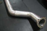
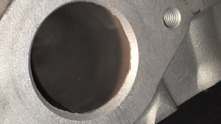
I also cleaned up the exhaust ports both
around the seats and at the header interface
using sanding rolls as shown below. The
ceramic often does not line up with the
casting and this can be smoothed out to a
large extent. |
|
|
 |
|
Before |
 |
|
After |
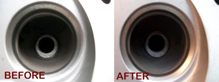 |
|
|
|
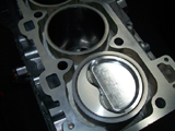
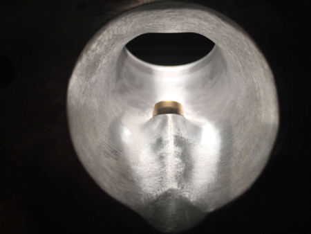
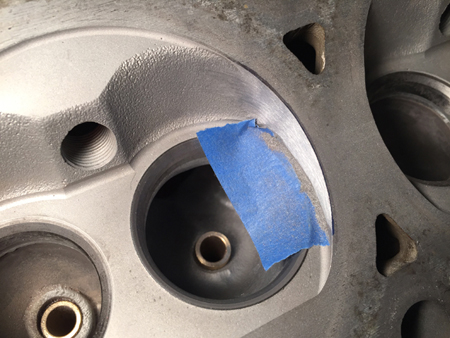
I also did some work to the chamber to
de-shroud the intake valves. My bore size is
102.3 mm and therefore I could remove some
chamber material. I used the head gasket to
determine how much material could safely be
removed. I marked the deck with a Sharpie as
a guide then used sanding rolls to remove
material as shown below. I was very careful
not to damage the seats. |
|
|
 |
|
|
|
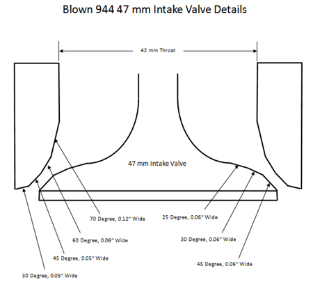
Once this work was completed, the head was
send back to the machine shop to have the
valve job done and to be assembled. The
valve job is SUPER important. Choose a shop
wisely. The intake dimensions I used were
developed by blown 944 (Sid) and I used them
with great results. |
|
|
 |
|
|
|
The intake valves are one piece valves and
were purchased from SI Valves for $27/each.
SI has stock intake valves (45mm) and +1
(46mm), +2 (47mm), and +3 (47mm). I used
47mm valves due to my bore size (102.2mm).
On my flow bench I found very little
improvement in flow was obtained above 47mm
for my bore size. The exhaust valves are the
stock sodium filled valves. |
|
|
 |
|
|
|
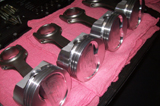
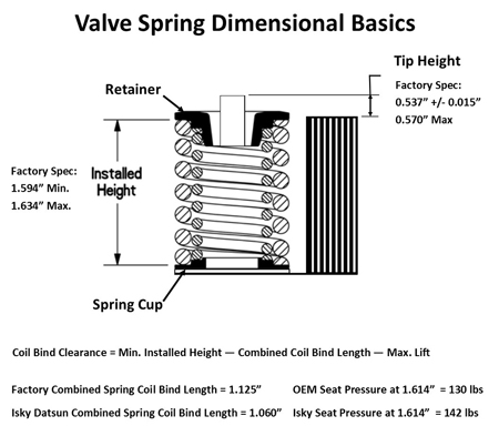
Shown below are some basics with respect to
valve springs. The first head I built, I was
pretty ignorant to these details. Do your
self a favor and get familiar with this
diagram. Do not assume the shop you use will
get the details right. Verify EVERYTHING. |
|
|
 |
|
|
|
I was intending to run a high lift cam
(0.525" intake lift) and using the formula
above it became clear that the stock springs
were going to bind. In an effort to find a
low cost solution I was able to find some
springs for a Datsun 280Z that fit perfectly
in the stock retainer and spring cup and
provided a bit more seat pressure (138 lbs
vs 130 lbs) while having 0.065" more spring
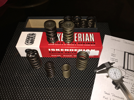
travel. The springs are made by Isky Cams
(ISK7005-8). As an added bonus, the springs
are half the price of the stock springs. |
|
|
 |
|
|
|
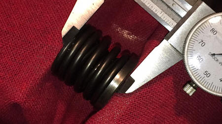
I was able to measure combined coil bind
length using a vise and calipers as shown
below. Coil bind clearance would be defined
as the amount of spring travel remaining
before coil bind at the minimum spring
height. A safe minimum coil bind clearance
would be 0.060". Some have run as low as
0.030" coil bind clearance in race
environments. Running these low of
clearances requires real precision in
determining the physical dimensions of each
valve. Also, keep in mind that as clearance
is reduced, spring life is also impacted. |
|
|
 |
|
|
|
I had the head decked a few thousands just
to clean things up for the Cometic MLS
gasket. |
|
|
 |
|
|
|
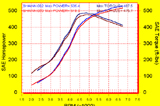
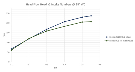
The completed head was flowed on a Superflow
flow bench at 28 inwc and the results are
shown below. The results show that cleaning
up the exhaust port and having a proper
competition valve job makes a huge
difference in an already outstanding exhaust
port. Also, the larger valve size in
conjunction with proper seat and throat
dimensions resulted in significant
improvement in intake flow. |
|
|
 |
|
|
|
|